Digital Dice - Electronic Random Number Generator
Overview
A classic digital dice circuit that generates random numbers from 1 to 6, displayed on a 7-segment display. When you press the button, the 555 timer oscillates at high frequency through a counter, creating a pseudo-random number generator. Releasing the button stops the counter and displays the result.
This project demonstrates fundamental digital electronics principles including timer circuits, binary counting, BCD-to-7-segment decoding, and PCB design. Perfect for learning the building blocks of digital logic systems.
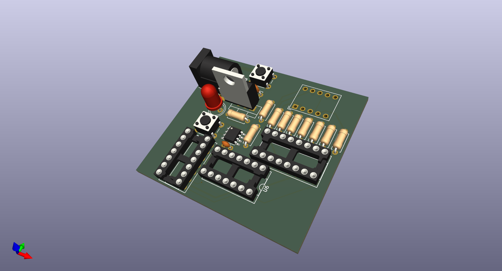
Digital Dice PCB - 3D Render
Key Features
- True random generation using 555 timer high-frequency oscillator
- Single 7-segment display shows numbers 1-6
- Push-button operation - press to roll, release to stop
- Power indicator LED for status
- Regulated 5V power supply with LM7805
- Classic TTL logic using 74LS series ICs
- Barrel jack input for easy powering (7-12V DC)
- Through-hole components for easy hand assembly
How It Works
Power Supply Section: The LM7805 voltage regulator converts the 7-12V input from the barrel jack to a stable 5V required by the logic ICs. Filtering capacitors (0.33µF and 0.1µF) ensure clean, stable power throughout the circuit.
Clock Generator (555 Timer): The NE555 is configured as an astable multivibrator, generating a high-frequency square wave around 100kHz. The frequency is set by resistor R10 (100kΩ) and capacitor C4 (0.01µF). When the button is pressed, this rapid oscillation drives the counter.
Counter (74LS90): The 74LS90 decade counter receives clock pulses from the 555 timer and counts in binary-coded decimal (BCD). The 74LS11 triple AND gate is used to configure the counter to reset after reaching 6, creating a true dice effect that only counts 1-6 instead of 0-9.
Display Driver (74LS47): The 74LS47 BCD-to-7-segment decoder converts the binary count from the 74LS90 into the appropriate segments to light up on the display. Current-limiting resistors (220Ω) protect the LED segments from excessive current while maintaining good brightness.
Technical Specifications
Bill of Materials
Integrated Circuits:
- U1: NE555D - Timer IC (DIP-8)
- U2: 74LS90 - Decade Counter (DIP-14)
- U3: 74LS47 - BCD to 7-Segment Decoder (DIP-16)
- U4: SC39-11EWA - 7-Segment Display, Common Cathode
- U5: LM7805 - 5V Voltage Regulator (TO-220)
- U6: 74LS11 - Triple 3-input AND Gate (DIP-14)
Passive Components:
- R1, R2: 10kΩ resistor (×2) - Pull-up/Pull-down
- R5: 220Ω resistor - LED current limiting
- R10: 100kΩ resistor - 555 timing
- C3: 0.1µF ceramic capacitor - Power decoupling
- C4: 0.01µF ceramic capacitor - 555 timing
- C5: 0.33µF electrolytic capacitor - Voltage regulation
Other Components:
- D1: Red LED 5mm - Power indicator
- SW1, SW2: Tactile push buttons
- J1: DC Barrel Jack (2.1mm center positive)
- IC Sockets: DIP-8, DIP-14, DIP-16 (recommended)
Estimated total component cost: $5-10 USD
Schematic & PCB Design
The schematic is organized into four logical sections: power supply, clock generator, counter/random number generator, and display output. This modular approach makes the circuit easy to understand, troubleshoot, and modify.
Digital Dice Schematic - Complete Circuit
The PCB layout prioritizes clean signal routing and proper power distribution. Ground and power traces are kept wide to minimize resistance and voltage drops. The 7-segment display is positioned for easy viewing, while components are arranged to minimize trace lengths and reduce noise.
Assembly Instructions
Step 1: Install IC sockets first (highly recommended). This allows you to swap ICs easily if troubleshooting is needed and prevents damage from soldering heat.
Step 2: Solder resistors and small ceramic capacitors (C3, C4). These components are heat-resistant and serve as good practice for beginners.
Step 3: Install the electrolytic capacitor (C5) - pay attention to polarity! The negative leg (marked with a stripe) goes to ground.
Step 4: Mount the LM7805 voltage regulator. A small heatsink is optional but recommended if you're using higher input voltages (10-12V).
Step 5: Install the barrel jack, push buttons, and LED (watch polarity - long leg is positive).
Step 6: Mount the 7-segment display last. Double-check the datasheet pinout - installing it backwards won't damage it, but it won't work!
Step 7: Insert ICs into their sockets, being careful to match pin 1 (look for the notch or dot). Gently bend pins if needed to fit the socket.
Step 8: Before powering on, visually inspect all solder joints and verify there are no shorts between traces. Use a multimeter to check that 5V appears at the regulator output before inserting ICs.
Usage & Operation
1. Power Connection: Connect a 7-12V DC power adapter to the barrel jack (center positive). The power LED should illuminate immediately.
2. Rolling the Dice: Press and hold the button. You'll see the display rapidly cycling through numbers as the counter runs at high speed.
3. Getting Your Result: Release the button at any time. The display will freeze on whatever number the counter was at - that's your random result (1-6)!
4. Roll Again: Simply press the button again. Each press creates a new random number based on the precise timing of when you release the button.
Why is this random? The 555 timer oscillates at approximately 100,000 times per second - far too fast for any human to time precisely. When you release the button, the exact moment is unpredictable, making the result effectively random!
Skills Demonstrated
- Digital logic design - counters, decoders, and logic gates
- 555 timer circuits - astable multivibrator configuration
- Power supply design - voltage regulation and filtering
- PCB layout and design using KiCad
- Through-hole component assembly and soldering
- BCD (Binary-Coded Decimal) and 7-segment display interfacing
- Schematic capture and documentation
- Manufacturing-ready design - gerber file generation
Troubleshooting Tips
Display shows nothing: Check power connections first. Verify 5V at the regulator output. Ensure ICs are inserted correctly (pin 1 orientation). Check that the 7-segment display isn't installed backwards.
Display shows wrong numbers: Verify connections between 74LS90 counter and 74LS47 decoder. Check BCD output pins on the counter match decoder input pins.
Button doesn't work: Check continuity on the button. Verify pull-up/pull-down resistors are in place. Ensure 555 timer is receiving proper power and ground.
Always shows same number: 555 timer may not be oscillating. Check R10 and C4 values. Measure pin 3 (output) of the 555 with an oscilloscope or LED.
Numbers change without pressing button: Check for loose connections or intermittent solder joints. Verify decoupling capacitors are properly installed near ICs.
Future Improvements (v2.0)
- Add a second 7-segment display for "double dice" mode (2-12 range)
- Include piezo buzzer for sound effects when rolling
- Add "hold" button to freeze the display temporarily
- Create an SMD version for more compact size
- Battery power option with 9V battery clip and on/off switch
- Automatic roll mode with adjustable timer
- Add RGB LED for visual effects during rolling
Learning Resources
This project is an excellent introduction to several fundamental concepts in electronics:
- 555 Timer IC - Learn about one of the most versatile ICs ever created
- Binary and BCD counting - Understanding how digital systems count
- 7-segment displays - Common output device in embedded systems
- TTL logic families - The building blocks of digital electronics
- PCB design workflow - From schematic to manufactured board
Perfect for beginners in electronics, students learning digital logic, or anyone wanting hands-on experience with classic IC-based circuits!
Project Files & Resources
License: This project is open source hardware under the MIT License. Feel free to build, modify, and learn from the design. Attribution appreciated but not required!
If you build this project, I'd love to see it! Open an issue on GitHub with photos of your build.